|
Abstract:
The efficiency of an intramedullary nail fixation device, used
in cases of trochanteric and subtrochanteric fractures, is
defined by several parameters, two of which are the location and
the number of distal screws that are used. Towards this
direction, the present paper investigated the effect of the two
aforementioned characteristics implementing the finite element
method (FEM). The left proximal femur of a 93-year old man was
scanned and two series of full 3D models, introducing an
intramedullary Fi-nail, were developed. The first series,
consisting of five models, concerned the use of a single distal
screw inserted in five different distal locations. The second
series, consisting of four models, concerned the use of four
different pairs of distal screws. Each model was analyzed with
the FEM twice, first considering that the femur is fractured and
then considering that the fracture is healed. The main
conclusion derived from this investigation was that, for Fi-nails
with a single distal screw, stresses around the nail hole were
reduced with proximal placement of the distal screw but the area
around the nail hole where the lag screw is inserted becomes
more stressed. Furthermore, for Fi-nails with a pair of distal
screws, placing the pair of distal screws at a specific location
is most beneficial for the mechanical behavior of the femur/Fi-nail
assembly.
J.Orthopaedics 2009;6(4)e1
Keywords:
Intramedullary nailing;
proximal femoral
fractures; finite element method (FEM); contact analysis
Introduction:
Intramedullary nailing is an established surgical technique for
the treatment of proximal femoral fractures. Intramedullary nails are load-sharing devices, allowing the bone
to transmit compressive forces while maintaining axial alignment
[1].
The Fi-nail (Sanatmetal Ltd. Hungary) is
an implant designed for the
treatment of trochanteric and subtrochanteric fractures of the
proximal femur.
Implant failures have been reported in the literature mainly due
to lag screw cut-out
[2-4]
or fractures of the femoral shaft due
to excessive local stress loading around the distal locking
screws or near the nail tip [4].
As far as finite element investigations are concerned, Wang et
al. [5]
investigated the effects of nail length, nail distal stiffness
and material stiffness on the structural behavior of the system
while Sitthiseripratip et al. [6] investigated
the developed stresses in the trochanteric gamma nail (TGN)
throughout the healing process of the bone in the fracture zone.
On top of that, biomechanical studies of intramedullary nails
have also been reported [7, 8]. Furthermore,
with respect to the implanted nails, it has been reported that
titanium nails (Ti) had
increased biomechanical stability compared to stainless steel
nails during tests of torsion and compression for both
transverse and comminuted
fractures [9].
The present paper, using the FEM, investigated the effects of
the location of the distal screw, as well as the number of the
implanted distal screws in the stress fields developed on the
femur/ nail assembly.
Materials
and Methods:
Finite element models
The left proximal femur of a 93-year
old man, who had underwent an intramedullary nailing for a
trochanteric fracture of the right femur (fig.1a), was scanned
with computer tomography (CT) using 1mm slice thickness. The CT
dataset was imported into Mimics (medical image processing
software by Materialise N.V., Belgium) where a 3D graphic model
was created. The 3D model was then imported into Ansys ver.10
(Finite Element Analysis software).
A commercially Fi-nail was used
(nail: 219mm long, proximal diameter 15mm, distal diameter 10mm,
5º
valgus curvature). The lag screw was 90mm long, 10mm in diameter
and placed at 125º
with respect to the nail. The distal screw(s) had a 10mm
diameter. Based on this geometrical information, a 3D model of
the Fi-nail was first created in Ansys and then virtually
inserted into and aligned with the intramedullary canal of the
femur model. The lag screw was inserted below the femoral head
center and 10mm away from the outer boundary of the femoral
head, in accordance with Parker MJ [10]. In
addition, the distal screw(s) and the femoral fracture were
added (fig.1b). The fracture under consideration was type
31-A1.3 according to AO-ASIF and it was introduced as an
idealized plane gap of 2mm thickness in the trochanteric region.
The single distal screws were inserted as indicated in table 1.
The location L1 (fig.1a) is placed 162.5mm
from the proximal nail head, the other locations being 11.3mm
away from each other (five single-distal-screw configurations).
These positions of the distal screw are possible with the
current implant configuration. With respect to the pairs of
distal screws, one screw was considered to be fixed at the
location L1 and the other was placed at one of
the other Li,i=2,3,4,5 locations, its distance
from the proximal head being denoted as zp.
(four pairs-of-distal-screws configuration: ([L1, L2],
[L1, L3], [L1,
L4], [L1, L5)]).
In total, nine models were developed.
The femur and the implant were
meshed using eight-node brick elements (SOLID185), and ten-node
tetrahedral elements (SOLID92), respectively. The nail-endosteum,
the nail-lag screw interactions and the fracture interfaces were
modeled using contact surfaces (TARGEI70 and CONTA174). The
use of dissimilar element types for the different components of
the construct is due to the different geometry complexity of the
bone and the implant. A 0.1mm gap between the nail and the lag
screw was applied. In total, each model had approximately 420000
elements and 240000 nodes.
|
Location |
Distance   |
|

|
162,5 |
|

|
173,8 |
|

|
185,1 |
|

|
196,4 |
|

|
207,7 |
Table 1:
Locations of single distal screws
Material properties
Linear elastic properties were
attributed to all of the materials involved, as shown in table
2, even though the distribution of the elastic moduli of the
cortical and cancellous bone is slightly arbitrary [5,
11, 12].
|
|
Young modulus
 |
Poissons ratio
 |
|
Cortical bone |
17 |
0.30 |
|
Cancellous bone (intertrochanteric region) |
0.32 |
0.30 |
|
Cancellous bone (femoral head) |
1.3 |
0.30 |
|
Fi-nail (titanium) |
110 |
0.30 |
Table 2:
Muscles and joint reaction forces for the one-legged stance
phase configuration
|
|
Applied forces (N) |
|
|
A-P |
M-L |
S-I |
|
Joint reaction force |
130 |
1062 |
-2800 |
|
Abductor muscle force |
|
-430 |
1160 |
|
Ilio-tibia tract |
|
|
-1200 |
|
Iliopsoas |
-560 |
-78 |
525 |
Loading, boundary conditions and analysis
A one-legged stance-phase load
configuration was applied. This load case is analytically
described in table 3, while the distal end was fixed. All modes
were analyzed using a non-linear contact analysis approach.
Investigation strategy
A diagrammatic
presentation of the present investigation is shown in fig.3. In
total,
18 different analyses were carried out (nine models, each one
analyzed twice), divided as follows:
·
Case 1: fractured femur with a single distal screw (5
models)
·
Case 2: healed femur with a single distal screw (5 models)
·
Case 3: fractured femur with a pair of distal screws (4
models)
·
Case 4: healed femur with a pair of distal screws (4
models)
For
the
examined
models, the stress fields were recorded for:
·
the distal screw (the screw itself and the area around the
corresponding nail hole)
·
the lag screw (the screw itself and the area around the
corresponding nail hole)
·
the proximal femoral head
Evaluation of results
The quantities explicitly recorded were:
·
the von Mises equivalent stress,
·
the nodal displacement of the femoral head, denoting, in the
case of the fractured femur, the dislocation of the fractured
femoral parts and in the case of the intact femur, the
deformation of the femur.
The quantities expressed in a normalized form
aimed at revealing how much stressed a screw is with respect to
its corresponding nail hole (relative stress state)
were defined as:
   (1) (1)
where
 stands for Normalized
Index, stands for Normalized
Index,
 is
the maximum von Mises equivalent stress, while
and is
the maximum von Mises equivalent stress, while
and
 are defined in section 2.1.
The stresses, the displacements and the normalized indices were
first recorded for the analyses carried out (section 2.3) and
then plotted versus distance are defined in section 2.1.
The stresses, the displacements and the normalized indices were
first recorded for the analyses carried out (section 2.3) and
then plotted versus distance
 ( ( for
models with a single distal screw, for
models with a single distal screw,
 for
models with a pair of distal screws), as follows: for
models with a pair of distal screws), as follows:
·
Distribution of the maximum von Mises equivalent stress versus
,
·
Distribution of the maximum proximal femoral head displacement
versus
,
·
Distribution of the Normalized Indices (Eq.(1)) describing the
change in the mechanical behaviour, versus
.
Overall, the evaluation procedure was carried out in four steps:
Step E1:Separate evaluation of each case using the
aforementioned plots
Step E2: Comparison between fractured and healed femur, for a
single and a pair of distal screws
Step E3:
Evaluation of each case using the Normalized Indices

Step E4: Comparison between a single distal screw and
a pair of distal screws, for fractured and healed femur
The aforementioned
steps are denoted in fig.3, with the code names EXyz,
where X stands for a numerical index (1 for Step E1,
2 for Step E2, etc), the subscript y refers to the
number of distal screws (s and p denote a
single distal screw and a pair of distal screws,
respectively), while the subscript z refers to the
type of femur ( f and i denote fractured and
healed femur, respectively).
Results :
Indicative stress and displacement fields are illustrated in
fig.2. When the fracture is taken into consideration, the
discontinuity of the displacement field at the area of fracture
is clearly shown in fig.2a. On the contrary, when the fracture
is
considered to be
healed, thus material continuity at the area of the fracture is
ensured, the corresponding displacement field is continuous, as
fig.2b illustrates. Finally, in case where a pair of distal
screws is used, the area around the proximal distal screw, the
screw itself and the corresponding nail hole, is more stressed,
as fig.2c shows.
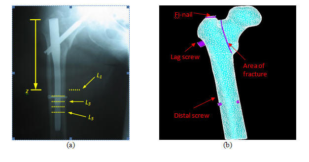
Figure 1:
(a) X-ray with the examined locations
 of distal screws marked as dotted lines and
(b) full 3-D model of the fractured proximal femur carrying a Fi-nail of distal screws marked as dotted lines and
(b) full 3-D model of the fractured proximal femur carrying a Fi-nail
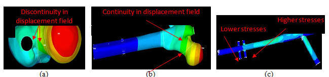
Figure 2:
(a) Discontinuous displacement field for a fractured femur, (b)
continuous displacement field for a healed femur and (c) stress
field for a Fi-nail with a pair of distal screws

Figure 3:
Diagrammatic presentation of the investigation carried out

(a)

(b)
Figure 4:
Maximum von Mises equivalent stress versus distance
for (a) the distal screw and (b) the lag
screw (case: fractured femur, single distal screw)

(a)

(b)
Figure 5: (a)
Maximum displacement of the femoral head and (b) Normalized
Indices versus distance
(case: fractured femur, single distal screw)

(a)

(b)
Figure 6:
Maximum von Mises equivalent stress versus distance
for (a) the distal screw and (b) the lag
screw (case: healed femur, single distal screw)

(a)

(b)
Figure 7: (a)
Maximum displacement of the femoral head and (b) Normalized
Indices versus distance
(case: healed femur, single distal screw)

(a)

(b)
Figure 8:
Maximum von Mises
equivalent stress versus distance
 for (a) the distal screw located at
and (b) the distal screw located at
(case: fractured femur, pair of distal
screws) for (a) the distal screw located at
and (b) the distal screw located at
(case: fractured femur, pair of distal
screws)

(a)

(b)
Figure 9:
(a) Maximum von Mises
equivalent stress for the lag screw and (b) maximum displacement
of the femoral head versus distance
(case: fractured femur, pair of distal
screws)

(a)

(b)
Figure 10:
Maximum von Mises
equivalent stress versus distance
for (a) the distal screw located at
and (b) the distal screw located at
(case: healed femur, pair of distal screws)

(a)

(b)
Figure 11:
(a) Maximum von Mises
equivalent stress for the lag screw and (b) maximum displacement
of the femoral head versus distance
(case: healed femur, pair of distal screws)

(a)

(b)
Figure 12:
Normalized Indices
versus distance for (a) a single distal screw and (b) a pair
of distal screws
Evaluation of each examined case
separately
Case 1: Fractured femur with a
single distal screw
The plots in fig.4a illustrate that
the maximum equivalent von Mises stress increases linearly with
respect to the distance
of the distal screw from the proximal end of
the nail. As the distance increases, so does the maximum
equivalent von Mises stress (fig.4a). Fig.4b shows that the
maximum von Mises stress developed on the lag screw is almost
insensitive to the distance
, while the maximum von Mises stress,
developed on the nail and around the hole where the lag screw is
inserted, decreases with respect to the distance
. From fig.5a, it yields that the maximum
displacement of the femoral head increases almost linearly.
Finally, the maximum von Mises stress at the fracture zone was
recorded to be  . .
Case 2: Healed femur with a single
distal screw
The plots in fig.6 are similar to
those in fig.4. From fig.6a, it is clear that the maximum
equivalent von Mises stress is linearly correlated to the
distance . From fig.6b, it yields that the maximum von
Mises stress developed on the lag screw is almost insensitive to
the distance . It is clear that the distally placement of
the single distal screw is more beneficial to the stress field
of the nail hole for the lag screw, but it has the opposite
effect to the stress field of the nail hole for the distal
screw. From fig.7a, it yields that the maximum displacement of
the femoral head increases linearly with respect to the distance
 . .
Case 3: Fractured femur with a pair
of distal screws
From fig.8a it is evident that the
plotted maximum equivalent von Mises stresses are practically
constant. Fig.8b shows that there is strong linear correlation
between the illustrated maximum equivalent von Mises and the
distance  and fig.9a suggests that the plotted maximum
equivalent von Mises stress are practically constant. Finally,
the maximum von Mises stress developed along the fracture zone
was and fig.9a suggests that the plotted maximum
equivalent von Mises stress are practically constant. Finally,
the maximum von Mises stress developed along the fracture zone
was  . .
Case 4: Healed femur with a pair of
distal screws
The plots in fig.10 and fig.11a
illustrate changes of the maximum equivalent von Mises stress
with respect to the distance
. Fig.10 shows that there is a strong linear
correlation between the plotted maximum equivalent von Mises
stress and the distance
. and fig.11a suggests a linear correlation of
the plotted quantities but for a more narrow range. From
fig.11b, it yields that the displacement of the proximal femoral
head decreases as the distance
increases. Finally, it was found that the
strains on the part of the bone where the second distal screw is
inserted are always higher than the corresponding strains on the
part of the bone where the first distal screw is inserted.
Comparison between fractured and healed femur
Comparison between Case 1 and Case 2
The results [figs.(4,5) and
figs.(6,7)] indicate that the stresses in the Fi-nail are
gradually reduced during the healing process of the bone in the
fracture zone. More particularly, the maximum von Mises stress
for
the fractured
femur in correlation
to
the healed femur
is:
·
higher on the distal screw ( -
) -
)
·
higher on the corresponding nail hole ( -
 ), ),
·
higher on the lag screw ( -
), and
·
higher on the corresponding nail hole ( -
).
Furthermore, the maximum
displacement of the femoral head is also higher ( -
).
Comparison between Case 3 and Case 4
A comparison between figs.(8,9) and
figs.(10,11), using
the healed femur as reference,
shows that
the maximum von Mises stress of the fractured
femur is higher:
·
on the distal screw at
 (-), (-),
·
on the corresponding nail hole ( -
),
·
on the distal screw at
 ( ( -), -),
·
on the corresponding nail hole ( -
),
·
on the lag screw ( -
), and
·
on the corresponding nail hole ( -
).
The maximum displacement of the
femoral head is also higher ( -
).
Evaluation of each case using the
Normalized Indices
At the fractured femur with a single
distal screw, the relative stress state is almost constant at a
value of , while, for the lag screw, it increases
linearly with respect to the distance
(fig.5b).
At the healed femur with a single
distal screw, the relative stress state presents a linear
decrease for the distal screw,, while for the lag screw, the
relative stress state increases linearly with respect to the
distance (fig.7b).
At the fractured femur with a pair
of distal screws (fig.12a), both the distal screw at
and the distal screw at
 present a correlation of 2nd
degree polynomial (relative coefficient present a correlation of 2nd
degree polynomial (relative coefficient
 in both cases). The maximum value for
normalized index concerning the distal screw at
appears for the pair of screws in both cases). The maximum value for
normalized index concerning the distal screw at
appears for the pair of screws
 . However, the maximum value for normalized
index concerning the distal screw at
appears for the pair of screws
. The normalized index concerning the lag
screw decreases slightly as the distance
increases. . However, the maximum value for normalized
index concerning the distal screw at
appears for the pair of screws
. The normalized index concerning the lag
screw decreases slightly as the distance
increases.
At the healed femur with a pair of
distal screws, for the distal screw at
a decrease up to
appears (fig. 12b) as the distance
increases, while for the distal screw at
a decrease up to
appears. For the lag screw, it appears a
constant normalized index.
Comparison between a single distal screw and a pair of distal
screws
For the fractured femur and when a
single distal screw, rather than a pair, is used, the developed
maximum von Mises stress is higher:
·
on the distal
screw at location at least by
,
·
on the corresponding nail hole at least by
, and
·
on the lag screw.
The opposite holds for
the corresponding nail hole. Furthermore, the proximal femoral
head displacement is approximately the same in both cases.
For the healed femur and when a
single distal screw, rather than a pair, is used, the developed
maximum von Mises stress is higher both on the distal screw at
location , and on the corresponding nail hole.
Furthermore, the maximum von Mises stress developed on the lag
screw is practically the same in both cases, while for the
corresponding nail hole, it is most beneficial to use a single
distal screw. Finally, the proximal femoral head displacement is
lower when a pair of distal screws is used, with the screws
being far away from each other.
Discussion :
For the models carrying a single
distal screw, the basic remark was that placing the distal screw
distally is beneficial to the proximal part but not to the
distal part of the nail. The more distally the distal screw is
placed the larger the cantilever, with respect to the distal
screw, of certain imposed force components becomes, thus
resulting in larger moments and in a generally more stressed
state.
With respect to the models carrying
a pair of distal screws, the basic remark was that placing the
distal screws far away from each other is beneficial to both the
proximal femoral head displacement and the stress state of the
distal Fi-nail part. A distal screw is nothing else than the
foundation of the Fi-nail in the intramedullary canal, thus as
the distance between two distal screws becomes larger, the
foundation of the implant becomes more rigid, causing lower
femoral head displacements.
The loads that are applied at the
femoral head and transmitted to the femoral shaft through the
distal screw(s). If two distal screws participate in this load
transmission, then the resulting stress state is lower than that
caused when only one distal screw is used because while the load
is the same there are two paths towards the femoral shaft
instead of one. Therefore, in general, the use of two distal
screws results in a less stressed nail near its distal end.
Conclusions:
The main conclusions of the present investigation are the
following:
· The
more distally a single distal screw is placed the more stressed
the screw itself and its corresponding hole on the Fi-nail get,
relieving at the same time the area around the nail hole of the
lag screw. This holds for both the fractured and the healed
femur.
· When
a pair of distal screws is introduced then, the distal area of
the nail generally gets less stressed while the opposite holds
for the area around the Fi-nail/lag screw connection. In
addition, the presence of two distal screws far away from each
other results in lower proximal femoral head displacements and
lower stressed distal part of the Fi-nail.
·
The stress field at the area of fracture is not significantly
influenced by the presence of a single distal screw or a pair of
distal screws.
Reference :
-
Knothe U, Knothe Tate ML, Klaue K,
Perren SM. Development and testing of a new self-locking
intramedullary nail system: testing of handling aspects and
mechanical properties. Injury, 2000, 31:617626.
-
Haynes RC, Poll RG, Miles AW, Weston
RB. Failure of femoral head fixation: a cadaveric analysis of
lag screw cut-out with the Gamma locking nail and AO dynamic
hip screw. Injury, 1997, 29:33741.
-
Kawaguchi S, Sawada K, Nabeta Y.
Cutting-out of the lag screw after internal fixation with the
Asiatic Gamma nail. Injury, 1998, 29:4753.
-
Vicario C, Marco F, Ortega L,
Alcobendas M, Dominguez I, Lopez- Duran L. Necrosis of the
femoral head after fixation of trochanteric fractures with
Gamma locking nail. A cause of late mechanical failure.
Injury, 2003, 34:12934.
-
Wang CJ, Brown CJ,Yettram AL, Procter P. Intramedullary nails:
some design features of the distal end.
Medical Engineering & Physics,
2003, 25:78994.
-
Sitthiseripratip K, Van Oosterwyck
H, Vander Sloten J, Mahaisavariya B, Bohez ELJ, Suwanprateeb
J, et al. Finite element study of trochanteric Gamma nail for
trochanteric fracture. Medical Engineering & Physics, 2003,
25:99106.
-
Seral B, Garcia JM, Cegonino J, Doblaré M, Seral F.
Finite element study of
intramedullary osteosynthesis in the treatment of trochanteric
fractures of the hip: gamma and PFN. Injury, 2004, 35:130-5.
-
Filardi V, Montanini R. Measurement
of local strains induced into the femur by trochanteric Gamma
nail implants with one or two distal screws. Medical
Engineering & Physics, 2007, 29;38-47.
-
Mahar AT, Lee SS, Lalonde FD,
Impelluso T, Newton PO. Biomechanical comparison of stainless
steel and titanium nails for fixation of simulated femoral
fractures. Journal of Pediatric Orthopaedics, 2004, 24(6):
63841.
-
Parker MJ. Cutting-out of the
dynamic hip screw related to its position. Journal of
Bone
and
Joint
Surgery
[BR],
1992, 74-B:625.
-
Wang CJ, Yettram AL, Yao MS, Procter P. Finite element
analysis of a Gamma nail within a fractured femur.
Medical Engineering & Physics,
1998, 20:677-683.
-
Brown CJ, Wang CJ, Yettram Al, Procter P. Intramedullary nails
with two lag screws. Clinical biomechanics, 2004, 19:519-525.
|