|
Abstract:
The
Total Shoulder Replacement (TSR) in patients with Proximal
Humeral Sarcoma (PHS) presents a challenge as standard
prostheses rely on the muscles of the shoulder joint for
stability. The loss of stability in PHS cases is due to the
resection of both the rotator cuff and deltoid muscles and
therefore the prosthesis requires built-in stability. This
report discusses three designs, which are the Quad-Point TSR,
the Hybrid-Screw TSR and the Central-Peg TSR. All three utilize
the same constrained ball-in-socket articulating design, which
links the glenoid and humeral components. Finite element
analysis (FEA) and experimental testing were carried out on the
ball-in-socket system. The ball-in-socket design was found to
have tensile and moment strengths of 900N and 15Nm respectively
and failure was noted when any part of the ultra high molecular
weight polyethylene (UHMWPE) socket experienced plastic
yielding. This link has a 90o range of mobility. All three
of the TSR designs incorporate modularity and suture holes in
their respective humeral components, while both cement and bone
screws have been used in the glenoid fixation. The use of
the coracoid process, as an extra fixation point for the glenoid
component, is possible as the coracoid process is exposed due to
the resection of the rotator cuff.
J.Orthopaedics 2007;4(3)e22
Keywords:
Shoulder Sarcoma; Proximal Humeral Sarcoma; Constrained
Shoulder; Reverse Shoulder Prosthesis.
Introduction:
Patients
with Proximal Humeral Sarcoma (PHS) require a Total Shoulder
Replacement (TSR) in order to salvage their upper limb. In most
cases, the sarcoma affects all of the primary stabilizing
muscles of the shoulder joint and as result built-in stability
is a requirement in the prosthesis design. This principle
conflicts with widely accepted designs, which attempt to
simulate the anatomical function of the shoulder joint.
Further difficulties associated with the presence of cancer are
the reduced availability of skin required for wound closure,
poor bone stock due to chemotherapy and varying levels of bone
resection 1.
This
work discusses three constrained total shoulder replacement
designs having the following criteria:
-
Modularity of
the components to accommodate for differing levels of
humeral resection,
-
Producing a low
prosthesis volume to ensure that enough skin is available
for wound closure,
-
Increased
glenoid fixation strength with both cement and screw
fixation
-
A constrained
link between the glenoid and the humeral components, which
provides a high range of mobility and strength.
Background:
Historical review
Neer reported the
first series of prosthetic shoulder arthroplasty in 1955 2, and
his designs were unconstrained. The prosthesis consisted of a
press fit cobalt chrome humeral head and in principle was
designed to recreate normal anatomy. Neers unconstrained
anatomical prostheses have become the standard for patients with
intact rotator cuff.
For the treatment
of more severe shoulder disorders, where for example, the
rotator cuff is deficient, constrained TSRs were developed
during the mid 1970s and early 1980s. Despite early favourable
results, most of the systems have been abandoned because of the
high incidence of complications.3,4,5,6. The complications
were due to loosening, instability and fracture of the
components because of the combined compressive and shear forces
leading to excessive stresses on the components and bone 7,8,9.
Operative
Principles
A proximal humeral
sarcoma can be detected as a growth just below the shoulder
joint. The only way to assess the cell type that makes up the
growth is to take a biopsy of the tissue. During the definitive
operation, the skin immediately surrounding the biopsy incision
is also removed, which reduces the amount of skin available to
close the wound. To facilitate closure of the wound the
implanted prosthesis must therefore have the lowest volume
possible.
When a sarcoma is
resected the objective of the surgery is to perform a wide
resection of the tumour containing a margin of health
tissue/musculature. This results in the loss of the rotator cuff
muscle group and often the axillary nerve, which supplies the
deltoid muscle. Very few of the shoulders stabilizing muscles
remain. The stability that these muscles once provided must now
be built into the prosthesis. There are however, remaining
segments of muscle, the extent of which largely depend on the
size and location of the tumour. This remaining muscle should be
attached to the prosthesis via suture holes, which will increase
the stability and may restore part of the joints active
function.
In resecting the
rotator cuff the surgeon can gain access to the coracoid
process, which can be utilised for additional anchorage thereby
enhancing the glenoid component fixation.
Market
Review
The Bayley-Walker
TSR is one of the only constrained total shoulder replacements
still available on the market today. It is based on the Kessel
design which resulted in a pain-free joint but was associated
with a high incidence rate of glenoid-fixation loosening 10. The
Bayley-Walker TSR is a reverse anatomy prosthesis which consists
of a titanium/UHMWPE glenoid component with a Co-Cr-Mo alloy
head 11 (Fig 1). It has been designed specifically for patients
with difficult reconstruction problems, rotator cuff
arthroplasty and disruption of the superior coraco-acromial arch
11. In addition, it has been used for treating bone tumours of
the proximal humerus where a segmental humeral component is
utilized, but it lacks the following features, which are
required in prostheses suitable for patients with PHS.
·
Suture holes are not provided for fixing any remaining muscle.
·
Modularity has not been built into the humeral stem to
accommodate different levels of resection
·
The use of cement in the fixation of the glenoid component is
not possible.
The aim of the
designs discussed in this paper is to address the above
deficiencies.
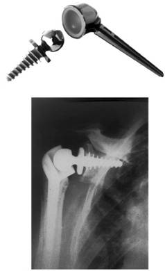
Fig
1. The Bayley-Walker shoulder joint (a) and the implanted
Bayley-Walker shoulder (b) 11.
Design
and development
Biomaterial
The
biocompatibility of Ti-6Al-4V, Co-Cr-Mo and UHMWPE is proven,
and the wear couple between Co-Cr-Mo and UHMWPE is a standard,
used for years.
Constrained Link
The
link between the humeral fixation and the glenoid fixation must
have some level of built-in stabilization otherwise the mass of
the limb may excessively load the remaining muscle which has
been sutured to the prosthesis and cause tearing of the tissue.
The constrained link is achieved by using a ball-in-socket
system, which only allows rotational motion. The ball-in-socket
design provides the least volume, which is a paramount factor to
ensure wound closure.
To
optimize the range of motion and the dislocation strength in
both tension and bending of the ball-in-socket system, FEA and
experimental testing was carried out using an ABAQUS linear
analysis and a Zwick tensile tester, respectively. In the
initial design the ball was press-fitted into a one-part UHMWPE
socket, after which the coupled ball-and-socket was inserted
into the housing (Fig 2).
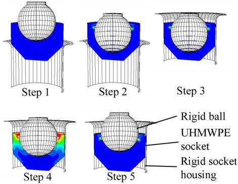
Fig
2. FEA simulation of the one-part socket design. Step1:
start of analysis, Step 2: the ball is inserted into the cup,
Step 3: The ball and cup are inserted into the housing, Step 4:
The ball begins to dislocate from the housing, Step 5: The ball
has been fully dislocated.
The
final ball-in-socket design (Fig 3) is based on the proposed
design by ISIQU Orthopaedics and consists of a Co-Cr-Mo
ball-and-stem articulating with a UHMWPE socket. The socket is
split beyond the equatorial plane. This system is housed in the
titanium body of the prosthesis and is locked together using a
ring clip. The socket is prevented from rotating by a Woodruff
key type peg.
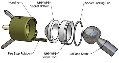
Fig
3. Constrained link assembly.
The
housing acts as a retainer preventing the UHMWPE from expanding
during the loading of the ball. The containment of the socket
increases the retention force of the system by 300% 12. The
limiting factor of this design is the minimum allowable entry
diameter of the socket before the ball produces plastic
deformation in the socket. Using a 20mm diameter ball the
minimum allowable entry diameter is 19.4mm. The design will
produce a maximum retention force of 400N at which point
dislocation begins to occur. The low retention force was
unacceptable and the design was modified and consisted of a
split socket. The ball is inserted into the top half of the
socket from below and the rest of the assembly process remains
the same as for a one part socket. Using this design it is
possible to generating a retention force of 900N before plastic
yielding of the UHMWPE occurred, using an entry diameter of 18mm
in 20mm diameter socket. The point at which the UHMWPE
experiences plastic yielding under the influence of a moment is
15Nm and the range of motion produced by the ball-in-socket is
90o (Fig 4).
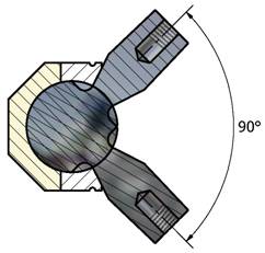
Fig
4. Range of motion of the ball-in-socket constrained link
design.
Discussion:
Comparison of designs
Glenoid
fixation and the orientation of the articulating ball
differentiate the three designs. Table 1 lists and quantifies
the factors that contribute to the performance of glenoid
fixation. The articulating ball can either be orientated
anatomically (on the humeral component) or in reverse (on the
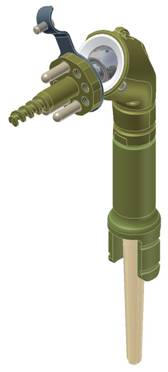
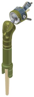
glenoid component) as shown in Fig 5.

(a)
(b)
(c)
Fig
5. Three constrained total shoulder replacement designs. (a)
Hybrid-Screw TSR, a reverse anatomical design , (b) Central-Peg
TSR, a reverse anatomical design and (c) Quad-Point TSR,
an anatomical design.
Table
1: The design factors.
|
Factor
|
Desired
|
Quad-Point
TSR
|
Hybrid-Screw
TSR
|
Central-Peg
TSR
|
|
Anatomical
or reverse ball and socket
|
-
|
Anatomical
|
Reverse
|
Reverse
|
|
Centre
of rotation from the glenoid face
|
min
|
18mm
|
24mm
|
24mm
|
|
Distance
from humeral shaft axis to glenoid face
|
min
|
46mm
|
41.4mm
|
41.4mm
|
|
Range
of
Mobility
(ROM)[1]
|
|
Elevation
|
160°
|
160°
|
160°
|
160°
|
|
Extension
|
60°
|
60°
|
60°
|
60°
|
|
External
Rotation in
Abduction
|
60°
|
52°
|
52°
|
52°
|
|
Internal
Rotation in
Abduction
|
60°
|
38°
|
38°
|
38°
|
|
Abduction[2]
|
140°
|
125°
|
125°
|
125°
|
|
Posterior
Reach
|
S1
|
None
|
None
|
None
|
|
Glenoid
Fixation Factors
|
|
Number
of screws used in the glenoid fixation
|
max
|
3
|
2
|
1
|
|
Number
of attachment points using cement as fixation
|
max
|
1
|
3
|
3
|
|
Volume
of Bone
Removed[3]
|
min
|
2.87cm3
|
4.67
cm3
|
5.16
cm3
|
|
Contact
area of cement
on
bone
|
max
|
9.2mm2
|
11.7
mm2
|
11.7
mm2
|
|
Contact
area of cement
on
prosthesis
|
max
|
5.2
mm2
|
6.4
mm2
|
6.4
mm2
|
|
Contact
area of prosthesis on bone
|
max
|
14.1
mm2
|
17.7
mm2
|
18.7
mm2
|
Glenoid fixation
Loosening
of the glenoid component is a major cause of failure in
unconstrained total shoulder arthroplasty 13. In the case of
constrained devices, glenoid fixation is exposed to higher shear
loads as all shear loading is transferred from the humerus to
the glenoid fixation due to the devices inability to
translate. In the past, constrained devices failed when
they were implanted in patients with intact rotator cuff and
deltoid muscles 14. This may be attributed to high loading
and usage conditions of the limb. In the case of PHS patients
the lack of muscle prevents much of the loading activity and the
main function of the prosthesis is to salvage the limb and allow
the patient to have the function of the forearm for activities
such as writing, typing and personal hygiene.
In
the case of constrained prostheses it is especially important to
have strong initial fixation to the glenoid and this is achieved
using screws and cement. For the long term survival of the
device, bone growth is required for secondary fixation. It is
important that as little bone as possible is removed from the
glenoid to maintain the overall strength of the glenoid bone
structure.
The
coracoid process is freed up when the rotator cuff muscle group
is resected and it is possible to utilize this structure as an
extra point of attachment for the glenoid fixation. A plate is
fixed to the primary glenoid attachment and a screw fixes the
plate to the neck of the coracoid process (Fig 6). The only
other design that attempted to have an offset fixation point is
that of Kölbel 1987, where he used a flange bolted to the base
of the scapula spine 15.
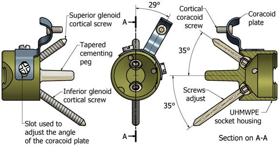
Fig
6. Showing the Quad-Point glenoid fixation system, notice
the coracoid plate and screw.
Quad-Point TSR
The
design utilizes some of the concepts used in Depuys Delta III
reverse total shoulder replacement. Instead of having a
Hydroxy Apatite (HA) coated central stem and four glenoid
screws, (where two are locked in place and two have a locating
window of 20 degrees) 16, the Quad-Point TSR design uses a
cemented central stem and two locating screws, (one superiorly
and one inferiorly). A coracoid plate is fixed to the titanium
housing using two screws and it is attached to the neck of the
coracoid process using one cortical screw (Fig 6).
The
design strengths (see Table 1):
-
The centre of
rotation is located close to the glenoid face.
-
The primary
fixation is with three screw points and a cemented central
stem
-
The screws that
are inserted into the glenoid can be locked at variable
angles.
-
The UHMWPE
socket prevents the glenoid screws from loosening.
-
The amount of
bone removed is low
-
The volume of
the prosthesis is low at the proximal end of the humerus
component, which reduces the amount of skin needed to close
the wound.
The
design weaknesses:
Hybrid-Screw TSR
The
design is a modification of the Bayley-Walker TSR, (Fig 1), with
the addition of cement fixation, a coracoid fixation screw,
modularity in the humeral component and suture holes. To reduce
the possibility of the glenoid splitting, while inserting the
central screw, the central stem is threaded only at the end.
This provides the required space for the three-cemented screws
peripherally positioned to the central screw. The screws serve
two functions one is to facilitate glenoid fixation and the
other to lock the coracoid plate into place. Once the system is
assembled the glenoid component is fixed to the coracoid process
by a cortical screw. Finally the ball is locked into place.
The
design strengths (see Table 1):
The
design weaknesses:
Central-Peg TSR
This design is a
simpler version of the Hybrid-Screw TSR. The idea is to reduce
the complexity of the assembly process and the risk of splitting
the glenoid. To achieve the above the central screw is replaced
with a parallel central peg.
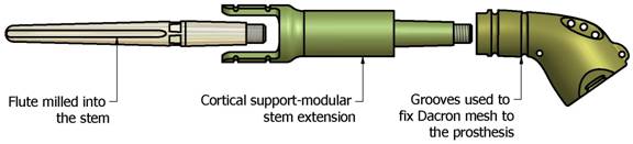
Humeral fixation
Regardless
of the type of humeral component fixation, aseptic loosening
remains remarkably uncommon at this interface. The design given
for all three TSRs is a standard tapered stem with three flutes.
The stem is fitted with a Morse taper, which locks together with
a humeral stem extension. Cortical support plates, are
incorporated into the distal end of the humeral stem extension
(Fig 7) and (Fig 8). These may be required in cases where an
extended proximal humeral resection is necessary or poor bone
stock is present. The surfaces of the plates are grooved to
accommodate additional surgical tensioning cable. They are also
treated to promote osseointergration.
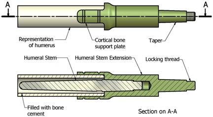
Fig
7. Humeral fixation
Modularity
In
cases with a PHS, the level of resection differs for every
patient. A surgeon has access to a variety of length humeral
stems and shaft extensions in case the resection margin is not
well defined and more bone needs to be resected.
Fig
8. The Humeral modular system
Conclusions:
The
number of cases requiring upper limb salvage is low and as a
result a constrained total shoulder system has not been made
available off the shelf. The Quad-Point TSR design shows the
potential to become an inexpensive modular system that will
cover the needs of patients with PHS. Of the three-glenoid
fixation designs the Quad-Point TSR design stands out as
possibly having the highest long term fixation strength of the
three. The moment transferred to the glenoid will be lower than
that of the other two designs due to an offset of only 18mm of
the centre of rotation from the glenoid face. Also the
volume of bone removed is low and the two-glenoid screws are
able to access bone superiorly and inferiorly to the glenoid.
The volume of the prosthesis is lower than the other two
designs, which facilitate ease of wound closure.
Acknowledgements:
The
authors would like to thank the technical staff of the
Mechanical Engineering Department at UCT, the orthopaedic
surgeons of
Vincent
Pallotti
Hospital
and the staff of ISIQU Orthopaedics. Their contributions in
their field of expertise brought this project to completion.
Also a special thanks to ISIQU Orthopaedics for the financial
support.
Reference :
- Rockwood, CA
Jr and Matsen, FA. The Shoulder, volume 1.
Saunders, 2nd edition, 1998.
- Neer, CS.
Articular replacement for the humeral head. Journal of Bone
and Joint Surgery, 37-A:215228, 1955.
- Wirth, MA
and Rockwood, CA. Current concepts review: complications of
total shoulder replacement arthroplasty. Journal of Bone and
Joint Surgery, 78-A:603 616, 1996.
- Neer, CS.
Glenohumeral arthroplasty. In: Neer CS (ed) shoulder
reconstruction. Philadelphia: WB Saunders, pages
143271, 1990.
- Brems, J.
The gleniod component in total shoulder arthroplasty.
Journal of Shoulder and Elbow Surgery,
2:4755, 1993.
- Cofield, RH.
Unconstrained total shoulder prostheses. Clinical
Orthopedics, 173:97, 1983.
- Collins, DN
and Harryman, T. Arthroplasty for arthritis and rotator cuff
deficiency. Orthopaedic Clinics of North
America, 28 (2):225, 1997.
- Post, M and
Jablon, M. Constrained total shoulder arthroplasty: long
term folllow-up observations. Clinical
Orthopaedics, 173:109, 1983.
- McElwain, JP
and English, E. The early results of porous-coated total
shouder arthroplasty. Clinical Orthopaedics,
216:217, 1987.
- Brostrom, L,
Wallenstein, R, Olsson, E, and Anderton, D. The Kessel
prosthesis in shoulder arthroplasty. Clinical
Orthopedics, 277:155, 1992.
- Ahir, SP,
Walker, PS, Squire-Taylor, CJ, Blunn, GW and Bayley, JIL.
Analysis of glenoid fixation for a reversed
anatomy fixed-fulcrum shoulder replacement. `Journal
of Biomechanics, 37:16991708, 2004.
- Author.
2005.
- Couteau, B,
Mansat, P, Estivalezes, E, Darmana, R, Mansat, M and Egan,
J. Finite element analysis of the
mechanical behavior of a scapula implanted with a
glenoid prosthesis. Clinical Biomechanics, 16:566575,
2001.
- Post, M,
Haskell, M and Jablon, SS. Total shoulder replacement with a
constrained prosthesis. Journal of Bone and
Joint Surgery, 62:327335, 1980.
- Kölbel, R,
Helbig, B and Blauth, W. Shoulder Replacement.
Springerverlag: New York, 1987.
- Boileau, P,
Watkinson, DJ, Hatzidakis, AM and Balg, F.
Grammont reverse prosthesis: Design, rationale, and
biomechanics. Journal of Shoulder and Elbow
Surgery, 14(1S):147S161S, 2005.
|